BIM-based
Parametric Model: Emerson College Los Angeles (ELA) by Morphosis
Arch
653 Building Information Modeling in Architecture
Spring 2017
Instructor: Dr. Wei Yan
Texas A&M University
Spring 2017
Instructor: Dr. Wei Yan
Texas A&M University
Project Description
This projects, according to the architect,
represents “a college campus condensed into urban site”. Emerson College Los Angeles (ELA) is located in
Hollywood, the center of entertainment industry and the second largest city in
the United States (figure 1). The site is 0.8 acres / 0.32 hectares and the
total area of the project is 120,000 ft² / 11,148 m². It was designed by Morphosis
Architects (Thom Mayne) between 2008 and 2011. The construction of ELA started
in 2008 and was finished in 2014.

The new facility hosts the seven disciples offered
by the School of Communication and the School of the Arts. It also has
workshops, lectures and others events to engage with alumni and LA community.
ELA’s program includes ground floor café and retail; classrooms, screening and
mixing rooms; outdoor terraces; housing for approximately 217 students, along
with faculty and staff; amenities, including a fitness center, lounge and
kitchen; bike facilities and three levels of below-grade parking.


The geometrical configuration of the facility is
composed of three essential components. First, two slim 10-story residential
towers, housing up to 217 students, that stand on the top on the parking floors.
Second, these two towers are bridged by multi-use rectangular platform. These
two components represent the residential zone and construct a frame to the
third component; two sculpted free-form in the central open volume. They
represent the academic building that hosts classrooms and administrative
offices
and defines multi-level terraces and active interstitial spaces to foster informal social activity.

Parametric Modeling Diagram
Conceptual
Mass
Option
One
In this option, all the masses of the building are created
in one conceptual mass (file).
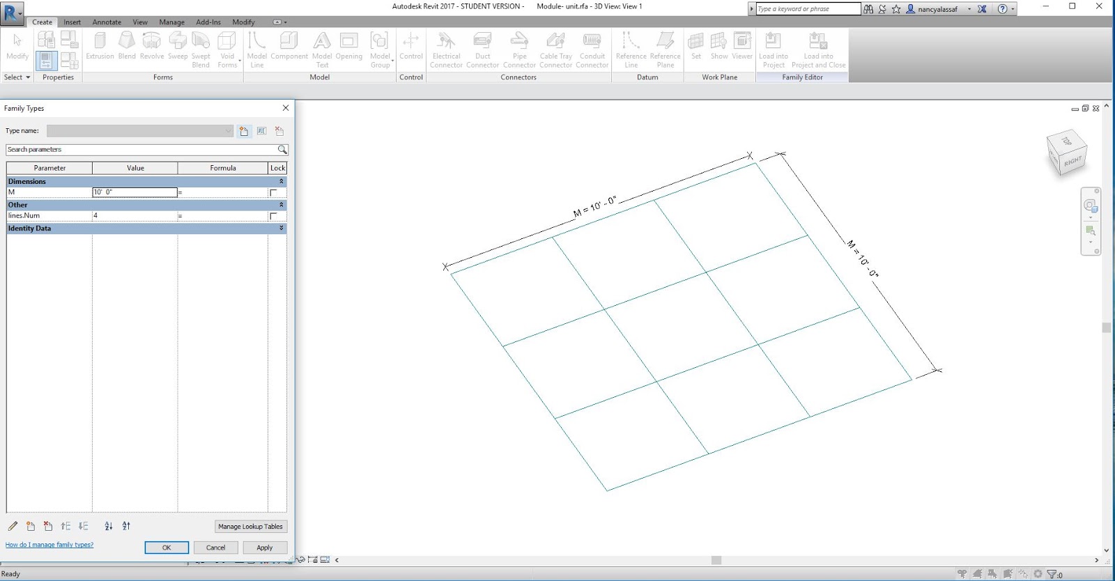
· As a start, a
morphological analysis was conducted to the building. The geometry of the
building follows 10 ft module on a larger scale and each 10 ft is divided into
3 parts. Accordingly, on a smaller scale the geometry follows 3 feet 4 inches
module.
· Second, one of the limitations
in Revit is that the option of module is only available in the project environment
(Work Plane). However, we can still have a module inside the conceptual mass as
a nested family. The 10 ft module is created as a separate family, then it’s
used to create a larger module via Array option in which the numbers of the
module units in the x and y direction are controlled through the array
parameters. Finally, this family (Generic model) is loaded into the conceptual
mass file to guide the creation of masses.
· Third, the geometry
of the building can be separated into two parts: First, the rectangular prisms
group which forms a container for the second part: curvilinear masses that
float in the middle.
o The parameters of
each rectangular prism include: the depth, width and height
o For the curvilinear
masses: they were created through using the command Loft on serval reference
planes and each plane has different orientation. Accordingly, to change the shape
of any mass, the profile can be accessed and updated. Another limitation
appears here, is changing the angel of the reference plane afterword. Revit
only allows the user to draw the reference plane in a specific angel from the beginning
but it cannot be rotated afterword.


· Note
o The higher number of
parameters (Length) in the Revit conceptual mass the harder for the user to
control them and their behavior.
o The control of some parameters
depends on which view you are using and what method. The height parameter in
this model for example can be controlled properly from the elevation view instead
of using the (Family type) dialog box.
Option
Two
To reduce the number of parameters and masses in
the previous model, this option separates the rectangular prisms masses and the
curvilinear masses into two separate conceptual mass files.
·
This option allows the user to try multiple
design options through changing the shapes of the masses that float in the
middle ( new families). For example, several design options of this part of the
design can be modeled in several conceptual mass files and the user can import each
one of them (as nested family) without remodeling the whole masses.
·
Passing parameter: In this option the mass offset
from the ground parameter (in the curvilinear conceptual mass file) = the podium
height (in the rectangular prisms conceptual mass file).
·
Pattern Based curtain walls: The pattern based curtain wall is
used to model several details in the project such as building skin, cladding
system and structural system (truss) as following:
o The first skin is a louver
system that covers the towers and the bridges. However, the angel of the
louvers change according to its location and the time. Therefore, one panel
with rotational parameter can actually fulfill this requirement.
§ First, a one strip of
the louvers is created (as a family) with a rotational parameter as well as length,
material, extrusion parameters.
§ Second, this family
is loaded into (curtain panel pattern based family) to create a 10 ft louvers
panel with rotation and material parameters.
§ Third, a plane in the
conceptual mass is divided by fix distance 10 ft in the u and v directions. Then,
the louvers panel is loaded and placed on this surface.
§ By changing the rotation
angel in the type parameter (create new type: angel = 0 instead of 90), the
closed louver skin can be created.
o To create the
cladding panels of the curvilinear masses:
§ The surfaces (in the
conceptual mass) are divided using 1\3 Step pattern.
§ And a (curtain panel
pattern based family) with 1\3 step pattern layout is used to create the panel.
It consists of a simple plane and a frame. The parameters of this panel are: material
parameter for the frame and the panel, the thickness of the panel and the dimensions
of the frame.
o The folded plates
skin: it consists of shifted folded steel plate hanged on steel rods.
§ The two planes (in
the conceptual mass) are divided using Rhomboid pattern (this pattern was used in
order to achieve the shifts in the arrangement of the plates).
§ And a (curtain panel
pattern based family) with Rhomboid pattern layout is used to create the panel.
It consists of circular rod in the middle, folded plate that can be controlled by
changing the location of the reference point.
§ Additionally, a
glazed panel and a frame were added to offer extra design options. And they can
be turned on or off through the visibility parameters.
§ one limitation
in modeling this skin is that the parameters of this skin (shape and spacing)
in the original design are based on a bitmap which cannot be done
through using Revit alone. Dynamo, a visual programming extension for
Autodesk Revit, can be used to overcome this limitation.
o The last pattern
based panel is a truss system
§ A (curtain panel
pattern based family) with Rectangular pattern is used to create a truss panel.
·
Limitations:
o Typically, after
modeling the curtain panel pattern based families and using them in the
conceptual mass file, the conceptual mass file should be loaded into the
project environment. However, the Revit gives warning if the size of the
file is larger than 10 mb because this might reduce the performance of the
project file. The size of the conceptual mass is 130 mb and loading a file with
this size into the project environment freezes Revit and the file keeps crashing.
o Accordingly, a possible
solution would be to load only conceptual mass file that is 10 mb or less.


Option
Three
In order to load a conceptual mass file that is 10 mb or less, the curtain
panel pattern based families cannot be part of the conceptual mass and they
need to be modeled separately inside the project environment as part of In-Place
conceptual mass.
Project
Environment
·
In the project environment, two conceptual masses
were loaded: the rectangular prisms mass and the curvilinear mass. Since the
skin in rectangular prisms mass are simple planes, then they are easy to be
created as In-place Mass in the project environment. Therefore, this mass file
was loaded without curtain panel pattern based families. However, the curvilinear
surfaces are harder to be modeled as In-Place Mass, therefore the curvilinear
was loaded with simplified curtain panel pattern based family ( only
panel , no frame).


·
In the project environment several details of the
project were added:
o Floor slabs
o Roofs
o Glazed curtain system
o Handrails
o Stairs
o Sit component and
landscape
o Furniture (for the dorms
part inside the towers)
o Doors


